
Marine chronometers: the watchmaking that made it possible to find longitude
For centuries, a navigator could determine latitude by observing the Sun or the stars, but still could not tell with sufficient accuracy how far he had travelled east or west. Longitude required a second reference: time. It was necessary to carry on board the time of a known meridian and compare it with the local time obtained astronomically. The marine chronometer was born to fulfil that mission — and, for watchmaking, it represented one of the most difficult technical problems ever set for a purely mechanical device.
This article approaches the subject mainly from the watchmaker’s point of view: the evolution of escapements, the management of motive power, temperature compensation, the balance and hairspring, gimbal suspension, rate trials and the different forms the naval chronometer took. It ends with a technical reading of the GUB No. 7986 kept on board the training ship Sagres (Navio-Escola Sagres).
NOTE: A marine chronometer is not a chronograph. A chronograph times independent intervals; a marine chronometer is a precision timekeeper, designed to keep a time reference as regular as possible for weeks or months, while subjected to temperature, humidity, vibration and the motion of the ship. It is at once a timepiece, a scientific instrument and a piece of navigation equipment.
1. Are there categories of marine chronometer? Yes — but no single universal classification
The word “chronometer” does not denote a specific physical form, but a timepiece designed and regulated to achieve high accuracy and, above all, very stable running. In the maritime context, it is useful to distinguish several categories that overlap historically.

The first is the box chronometer, or chronometer in a box: the classic instrument housed in a wooden box, with the movement contained in a metal vessel — the bowl — suspended in gimbals. This is the configuration we now most readily associate with the marine chronometer, and it is also the category of the GUB of the NRP Sagres.

Second, there are pocket chronometers: high-precision pocket watches, sometimes fitted with a detent escapement and with chronometric solutions similar to those used in marine instruments. John Arnold played a particularly important role in the development of this category. Not all of these watches were used as the main reference on board, but they showed that the principles of precision chronometry could be applied to much smaller and more portable instruments.

A third category of great practical importance is the deck watch, or watch for use on deck. On many ships, the main chronometer remained protected in its place of installation, while a high-precision portable watch, previously compared or synchronised with it, was taken up on deck during astronomical observations. This avoided moving the reference chronometer unnecessarily and reduced the risk of shock, change of position or disturbance to its rate.
Makers such as Ulysse Nardin, Longines, Hamilton and others produced high-quality deck watches for navies and hydrographic services.
It is also common to classify chronometers by their running time — one day, two days, eight days — although the designation does not always correspond exactly to the total going time. Two-day chronometers became very common: a reserve of more than 48 hours made it possible to wind them daily at the same hour, keeping the instrument away from the extreme zones of the mainspring’s force curve. There are also sidereal chronometers, intended to keep sidereal time for astronomical purposes, and observatory chronometers, whose classification derives mainly from their testing regime and scientific use.

Finally, we can distinguish mechanical, electromechanical and quartz chronometers. This technological classification becomes especially relevant in the twentieth century, when many navies kept mechanical chronometers for some time alongside electronic references before the definitive transition to quartz, radio and satellite.
2. Longitude: when four seconds can mean a nautical mile
The Earth turns through approximately 360 degrees in 24 hours. On average, therefore, a difference of one hour corresponds to 15 degrees of longitude, four minutes to one degree and four seconds of time to one minute of arc. At the equator, one minute of arc of longitude corresponds approximately to one nautical mile. This makes the demands of the problem immediately clear: a few seconds of accumulated error could translate into miles of uncertainty in position.

The chronometric method is based on comparing local time — obtained by astronomical observation — with the reference time kept by the chronometer. If local noon occurs when the chronometer shows, for example, 14:00 on the reference meridian, the two-hour difference represents approximately 30 degrees of longitude. The actual calculation requires astronomical and nautical corrections, but the principle is this: turning a time difference into an angle.
At the beginning of the eighteenth century there was no timepiece stable enough for this task on the open sea. A pendulum clock could be very accurate on land, but the pendulum reacts to the acceleration and heeling of the ship. A portable timepiece with a balance faced other problems: friction, irregular quality of springs, temperature variations, changes in amplitude, escapement errors and differences in rate between positions. Longitude therefore became a problem of astronomy applied to precision watchmaking.

GUB marine chronometer No. 7986 on board the training ship Sagres. Photograph by the author. ©IPR
3. Before Harrison: Sully, Le Roy, Berthoud and a more European story than it seems
The popular narrative tends to turn John Harrison into an isolated inventor who solved longitude single-handedly. Harrison was decisive, but the real chronology is much richer. From the end of the seventeenth century and throughout the eighteenth, English, French and Swiss watchmakers experimented with solutions designed to keep time at sea.
Some developed machines that failed, others arrived at technically remarkable solutions that were difficult to manufacture, and others created ideas that would only later be incorporated into the classic chronometer.
This is the only image that probably depicts Sully, on the left. Marine timekeeper by Henry Sully, Paris, 1724
Henry Sully (probably, on the left) and his chronometer, the Marine timekeeper by Henry Sully, Paris, 1724
Henry Sully, an Englishman settled in France, built marine timekeepers in the first decades of the eighteenth century and published important work on the subject. His instruments did not definitively solve the problem, but they belong to the lineage that precedes Harrison. Royal Museums Greenwich itself places Sully among the first chapters in the evolution of marine chronometry.
Portrait attributed to Pierre Le Roy (1717–1785)
Portrait attributed to Pierre Le Roy, diagram of his detent escapement and photo of his chronometer
In France, Pierre Le Roy was a fundamental figure. Horological historiography credits him with one of the first formulations of the detent escapement and, above all, with a very clear understanding that chronometric precision required functions to be separated: an oscillator as free as possible, a brief and controlled impulse, and compensation for the effects of temperature. Le Roy is one of the classic examples of a name of enormous technical importance that remains far less known to the public than Harrison.
Ferdinand Berthoud
Portrait of Ferdinand Berthoud and photos of his marine chronometer
Ferdinand Berthoud equally deserves a place in the foreground. He presented a design for a marine timekeeper to the French Royal Academy of Sciences in 1760, produced several experimental instruments, followed the European debate on Harrison at first hand and, from 1768, saw his timekeepers No. 6 and No. 8 tested on a voyage of just over a year. In 1770 he received the title of Horloger-Mécanicien du Roi et de la Marine and an order for twenty longitude timekeepers. Berthoud was no late imitator: he was a systematic researcher who published on the theory, construction, testing and use of marine timekeepers.
The history of longitude is, therefore, an international history. The mechanical solution did not appear in an instant; it took shape through the accumulation of experiments on escapements, compensation, springs, balances, materials, lubrication and testing methods. Harrison occupies the centre of the British narrative, but continental watchmaking developed solutions of enormous depth in parallel.
4. John Harrison: from H1 to H4 — four machines, four ways of thinking about the problem

Harrison began by tackling the problem as a maker of large-format clocks. H1, presented in 1735, is a monumental, almost architectural machine. Instead of a pendulum, it uses two large interconnected balances, so that the disturbances of the ship affect both in a compensating way. The whole adopts low-friction solutions and an obsessive concern with thermal stability and isochronism.

H2 refined some elements, but Harrison detected a fundamental problem in the behaviour of the system and decided not to submit it to the planned ocean trials.

H3 occupied Harrison for some nineteen years. It is technically fascinating because it contains ideas that go beyond navigation: bimetallic compensation elements and a roller-bearing system intended to reduce friction. Even so, the machine did not achieve the desired constancy. The most important point is that the partial failure of H3 pushed Harrison in a different direction: instead of continuing to increase the sophistication of a large machine, he moved towards the architecture of the portable watch.
Around 1751–1753, John Jefferys built a watch to Harrison’s specifications. The behaviour of that watch convinced Harrison that a relatively large balance, oscillating at high frequency and with great amplitude, could be more resistant to the disturbances of the ship than the large systems of paired balances. Thus H4 was born, begun in 1755 and completed in 1759.

H4 looks like an enormous pocket watch, but the resemblance is misleading. Its balance beats five times per second, very fast by the standards of the time, and with high energy. Harrison uses a profoundly refined verge escapement, with diamond pallets, and a remontoire/constant-force system intended to isolate the regulator from variations in the transmission. Contrary to what many summaries suggest, H4 is not yet the classic detent chronometer that would dominate the nineteenth century; it is a very personal solution of Harrison’s, enormously complex and difficult to reproduce.
John Harrison, H4, 1759. Illustration based on a photograph from the National Maritime Museum, Greenwich. John Harrison, H4, 1759. Illustration based on a photograph from the National Maritime Museum, Greenwich. John Harrison, H4, 1759. Illustration based on a photograph from the National Maritime Museum, Greenwich.
John Harrison, H4, 1759. About 13 cm in diameter, with a high-frequency, large-amplitude balance, Harrison’s fourth longitude timekeeper represented a radical change from the large earlier mechanisms. Illustration based on a photograph from the National Maritime Museum, Greenwich, inv. ZAA0037 (background altered).
H4’s trial voyages proved that the mechanical route could work. The instrument met the most demanding limits set by the Longitude Act, although the award of the full prize was politically and institutionally fraught. Harrison was eventually rewarded by Parliament, but the real question left unresolved was a different one:
how could an almost unrepeatable masterpiece be turned into an instrument that dozens or hundreds of ships could buy, maintain and use?
5. The next problem: working was not enough — it had to be manufacturable
Harrison demonstrated the possibility. Larcum Kendall, John Arnold and Thomas Earnshaw helped turn it into a reproducible technology. Kendall built K1 as a very faithful copy of H4. The instrument accompanied James Cook on his second voyage to the Pacific, between 1772 and 1775, and Cook recorded its accuracy favourably. K1 was enormously important because it showed that the solution could leave Harrison’s workshop and work in real service, even though the cost remained too high for widespread adoption.
John Arnold followed a different strategy: simplification. He developed lower-cost chronometers, worked intensively on compensation balances and helical hairsprings, and perfected the detent escapement. His No. 36, of 1778, is historically important and is associated with the establishment of the term chronometer for a portable precision timepiece. Arnold realised that the future lay not in copying H4 part by part, but in reducing the number of components, making adjustment more rational and bringing production closer to a commercial scale.
Oil portrait of John Arnold with his family, painted by Robert Davy between 1783 and 1787. John Arnold & Son marine chronometer, London, c. 1795. Photograph: Daderot / Wikimedia Commons, CC0.
Left: John Arnold with his family, accompanied by his son John Roger Arnold and his wife, Margaret. Painting by Robert Davy, c. 1783–1787. Clockmakers’ Museum / Science Museum Group. Right: John Arnold & Son marine chronometer, London, c. 1795. Photograph: Daderot / Wikimedia Commons, CC0.
Thomas Earnshaw took this simplification even further. The priority dispute between Arnold and Earnshaw over the spring detent escapement has never entirely disappeared from historiography, but the practical consequence is unequivocal: the configuration associated with Earnshaw became the dominant standard for the marine chronometer of the nineteenth and twentieth centuries. In 1804 the Board of Longitude even had models made of the systems of Earnshaw and John Roger Arnold in order to study the question. Both received rewards for their contribution to the advancement of marine timekeepers.
Thomas Earnshaw (1749–1829). Portrait with a chronometer of the type he helped to establish as the standard of marine chronometry. Thomas Earnshaw (1749–1829). Portrait with a chronometer of the type he helped to establish as the standard of marine chronometry.
Thomas Earnshaw (1749–1829). Portrait with a chronometer of the type he helped to establish as the standard of marine chronometry. National Maritime Museum, Greenwich.
Thomas Mudge, Josiah Emery and other makers also developed chronometers and escapements of great interest. The actual history is less linear than a sequence ‘Harrison → modern chronometer’: there are several competing technical families, and the selection of the final standard results as much from performance as from cost, ease of regulation, maintenance and production capacity.
6. The escapement: from Harrison to the detent

The escapement is the organ that converts the continuous energy of the wheel train into a sequence of impulses and, at the same time, allows the oscillator to set the rhythm of the timepiece. In a precision chronometer, the ideal is for the escapement to interfere as little as possible with the balance. The longer the balance is free, the less its period depends on the state of the power transmission, the lubrication or the geometry of the contact surfaces.
H4 is an important historical exception. Harrison used an extremely refined form of the verge escapement, normally regarded as an archaic escapement with strong recoil. With diamond pallets, high frequency, carefully controlled amplitudes and a sophisticated constant-force system, he managed to extract extraordinary performance from this principle. This shows that, in watchmaking, it is not enough to identify the ‘type’ of escapement: the quality of the complete design and of the adjustment can radically change the result.
Marine chronometer in a wooden box, suspended in gimbals. On the right, a view of the movement inside the bowl, highlighting the precision mechanical architecture typical of these instruments.
The route that eventually won was the detent escapement. In the pivoted detent version, the detent turns on pivots. In the spring detent version, the elastic element itself replaces the pivots and reduces friction. The principle is that of a detached escapement: for almost the whole oscillation, the balance is not in contact with the escapement. Only on one passage does the balance unlock the escape wheel and receive impulse; on the return swing, the system lets it pass without a new impulse.
The advantages are enormous: little sliding friction, a brief impulse close to a tangent, reduced need for lubrication on the critical surfaces and freedom of the balance for most of the cycle. The drawback is delicacy. The detent escapement is sensitive to shocks, requires very precise tolerances and, in many configurations, is not self-starting. In an everyday pocket watch this would be a problem; in a protected chronometer, mounted in gimbals and handled by professionals, the trade-off made sense.

Thomas Earnshaw chronometer associated with HMS Beagle. The movement uses a fusee, Harrison’s maintaining power, a spring-detent escapement, a compensated bimetallic balance and a free-sprung helical hairspring. Photograph: BabelStone / Wikimedia Commons, CC0.
7. The fusee (Fusée), chain and maintaining power: how to deliver force without spoiling the rate

The mainspring does not deliver the same torque when fully wound as when it nears the end of its reserve. In an ordinary watch, the escapement and regulator can tolerate part of this variation. In a marine chronometer, a change in balance amplitude can cause a change in rate and, therefore, an error in longitude. The fusee and chain is an elegant mechanical solution for linearising the delivery of force.
The spring drives a chain — or, in some chronometers, a flexible metal band — wound between the barrel and a conical part called the fusee. When the spring is strong, the chain acts on a zone of smaller radius; as the spring weakens, it moves to a zone with a longer lever arm. The profile of the fusee is calculated to compensate for the spring’s torque curve. The ideal result is a much more constant force applied to the train.
Another problem then arises: during winding, if the transmission is interrupted, the chronometer momentarily stops receiving energy. Harrison therefore developed a device to keep the timepiece going during winding, which keeps the wheel train powered at least while the mainspring is being wound. This mechanism became a classic feature of many high-quality chronometers and shows clearly how every operation liable to disturb the rate was treated as a potential source of chronometric error.
Regularity of winding was equally important. It was customary to wind the chronometer at approximately the same time every day, keeping it within a more predictable operating zone and avoiding unnecessary variations in the state of tension of the mainspring. The up-and-down indicator — Up/Down or Auf/Ab — was therefore not a decorative complication, but a functional element for monitoring the instrument.
8. Balance and hairspring: where precision is won or lost

The regulating organ is the real clock within the clock. The balance oscillates; the escapement converts those oscillations into the regular advance of the wheel train. In a classic chronometer the aim is a large balance, with high inertia, carefully poised and paired with a hairspring whose development is as concentric as possible. The cylindrical helical hairspring became a frequent solution because it allows more symmetrical expansion and contraction than many flat hairsprings of the period.
Many chronometers use a free-sprung balance (free-sprung), with no conventional regulator index to alter the active length of the hairspring. Regulation is done through the inertia of the balance, by means of masses or compensation screws. This eliminates a point of disturbance on the hairspring and makes the system potentially more stable. Fine adjustment, however, demands enormous skill.
Temperature was for a long time the great enemy. The elastic modulus of the steel of the hairspring varies with temperature; at the same time, the components of the balance expand. The cut bimetallic balance exploits the difference in expansion between two metals: as the temperature rises, the arms curl and move mass closer to the axis, compensating for the hairspring’s tendency to make the timepiece lose. Screws distributed around the rim allow the watchmaker to adjust the compensation carefully.
Even this solution is not perfect. A bimetallic balance can be correctly compensated at the extremes of a temperature range and still show an error at intermediate temperatures — the so-called middle-temperature error. In the nineteenth century auxiliary compensation systems appeared and, later, special alloys such as the Guillaume balance and hairsprings of low thermal sensitivity.
The history of the chronometer is, to a great extent, the history of a successive struggle against ever smaller errors.
9. Isochronism, amplitude, static poise of the balance and positional errors
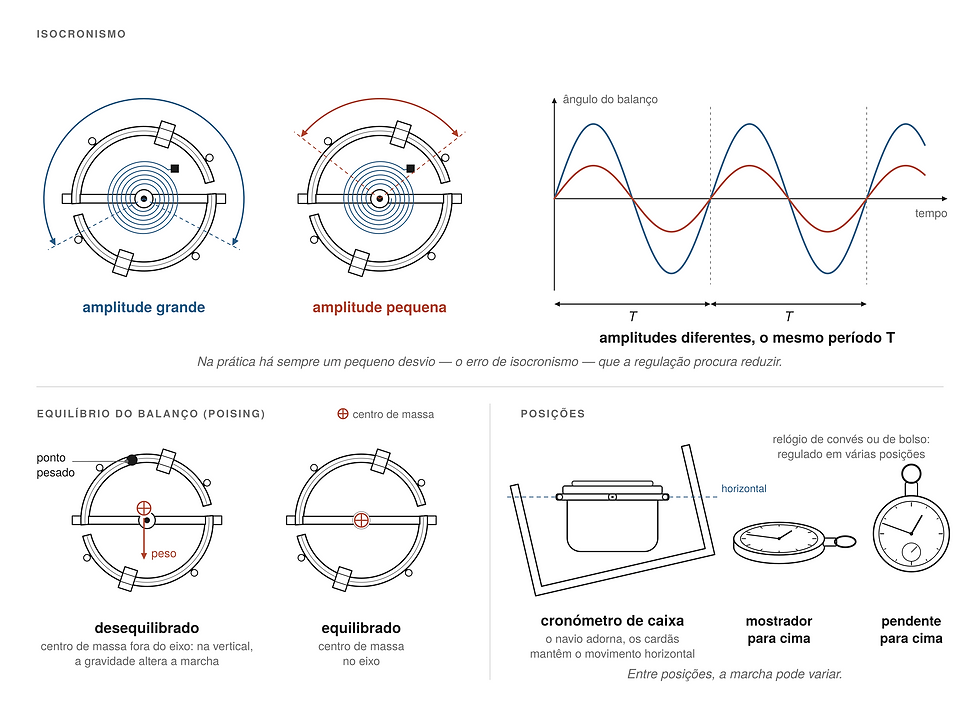
An ideal regulator would have the same period regardless of amplitude. In reality, changes in amplitude slightly alter the rate. The aim of isochronism is to reduce this dependence. The design of the hairspring, the shape of the terminal curves, the relationship between balance and hairspring, the constancy of force and the escapement all play a part in the result. That is why chronometry cannot be understood by looking at a single component in isolation.
The static poise of the balance — and, ideally, its dynamic poise too — is equally critical. If the centre of mass does not coincide with the axis, gravity introduces position-dependent errors. In a box chronometer, gimbal suspension reduces the range of positions of the movement, keeping it approximately horizontal, but it does not eliminate the need for precise poise. Deck watches and pocket chronometers, on the other hand, are adjusted to multiple positions because they spend much more time vertical or tilted.
End shake, the geometry of the pivots, the quality of the jewels and the viscosity of the lubricants also alter amplitude and rate. The chronometer is a system in which differences of micrometres, small contaminations or aged oil can become seconds per day. That is why servicing a chronometer requires the methods of precision watchmaking and not just ‘cleaning and oiling’.
10. Regulation and trials: the value lies in a known rate, not in showing the exact time today

An essential principle of naval chronometry is often misunderstood: it is not essential for the chronometer to show exactly the right time at every moment; it is essential to know its error and, above all, for its rate to be regular. If a chronometer gains 0.8 seconds a day in an extremely constant way, that deviation can be applied mathematically. A timepiece that is right today, loses three seconds tomorrow and gains two the day after is much less useful.
Observatories and hydrographic services developed systematic tests: rate at different temperatures, changes of position, variations in amplitude and extended periods of observation. The competitions and trials of the nineteenth and twentieth centuries were not mere commercial demonstrations; they functioned as laboratories where the stability of an instrument was assessed under standardised conditions.
A chronometer’s record sheet could log the daily difference from the standard. From that series the mean rate was obtained and variations were observed. For navigation, the officer applied the known error of the instrument to the time indicated.
This culture of measurement — measuring the error of the measuring instrument itself — is one of the most important ideas inherited from marine chronometry.
11. Gimbal suspension and the box: part of the mechanism, not mere furniture

The metal vessel containing the movement is mounted in two rings with perpendicular axes — the gimbal suspension. When the ship rolls or pitches, gravity tends to keep the inner assembly approximately horizontal. This reduces positional errors and protects the geometric relationship of the escapement and the regulator. That is why the suspension must be understood as a functional part of the chronometric instrument.
The wooden box also has precise functions: absorbing shocks, keeping out dust, protecting the glass and the suspension and allowing safe transport. Many have two-level lids, viewing windows, a compartment for the key and instruction plates. Some models include devices for locking the gimbals during transport. Carrying a chronometer unlocked, or setting it down without regard for the suspension, can produce stresses for which the system was not designed.
The Sagres chronometer in its box. The gimbal suspension, the transport box and the configuration of a naval instrument are visible. Photograph by the author.
12. How a chronometer was used on board

Before departure, the chronometer was compared with a known time reference.
On board, it was kept running continuously and the hands were normally not touched every day to ‘set’ it. The error and the rate were recorded. When it was necessary to obtain Greenwich time — or the time of another reference meridian — the calculated correction was applied to what the instrument showed.
Determining longitude by chronometer also involved a sextant, observations of the Sun or stars, nautical almanacs and calculation. The chronometer did not ‘give the position’; it supplied the indispensable time variable. The quality of the whole process depended as much on the watchmaking as on the observation and the mathematical discipline of the navigator.
On important ships it was common to have several chronometers. Comparing them made it possible to detect an abnormal change of rate in one instrument. Redundancy was essential because, in mid-ocean, a failure could not be solved simply by sending the instrument to the workshop. The deck watch, where there was one, was synchronised with the main chronometer and used to carry the time to the place of observation without moving the master instrument.
From the nineteenth century onwards, visual time signals in ports — such as time balls — and later the telegraph and radio made comparison and correction easier. Even so, the chronometer remained important as an autonomous back-up and as the link between astronomical observation and standard time.
13. Glashütte: when German chronometry goes to sea

During the nineteenth century Glashütte became a centre of precision watchmaking, and it began producing marine chronometers in 1886. The German tradition developed instruments for navies, observatories and commercial shipping, combining the international architecture of the classic chronometer with its own production and testing standards.
After the Second World War, the Glashütte industry, located in East Germany, was reorganised. In 1951 several companies were merged into VEB Glashütter Uhrenbetriebe, GUB. Production of mechanical marine chronometers continued for decades. The Deutsches Uhrenmuseum Glashütte documents, for example, GUB chronometer No. 8888 as produced in 1965 and states that the factory kept producing mechanical chronometers until 1978, alongside quartz chronometers from 1974.
GUB chronometers belong fully to the tradition of the box chronometer: a large movement, a chronometer escapement, a compensated balance, a hairspring suited to chronometric service, seconds and up-and-down indication, and gimbal suspension. The Glashütte school valued functional finishing and precision; in these instruments, decoration is secondary to stability and ease of maintenance.
14. The GUB No. 7986 of the training ship Sagres
In the photographs taken on board the training ship Sagres, a GUB chronometer — Glashütter Uhrenbetriebe — can clearly be identified, with the number 7986 on the dial. The layout is classic: central hours and minutes, small seconds at 6 o’clock, Roman numerals and a power-reserve indicator at 12 o’clock. The inscriptions ‘AUF’ and ‘AB’ are the German up-and-down indication.
GUB marine chronometer No. 7986 of the NRP Sagres, mounted in gimbals inside its wooden box, showing the main dial, the small seconds and the up-and-down indicator Auf/Ab. Photograph: IPR. © IPR
The assembly is mounted in a metal bowl suspended in gimbals inside a wooden box. The top-down reading and the high legibility of the dial were designed for instrument service. By comparison with documented GUB numbers, the number 7986 plausibly places this example in the early 1960s. The German museum itself states that it holds the sales records of GUB chronometers and can provide archival information.
It is equally important not to extrapolate too much from the dial. To document this example technically and definitively, it would be necessary to open the instrument under controlled conditions and photograph the movement: escapement, balance, hairspring, fusée, wheel train, maker’s marks, internal numbers and any signs of repair. In an instrument that has served for decades, parts may have been replaced and adjustments may not correspond exactly to the factory state.
The value of No. 7986 is twofold. It is a physical example of twentieth-century Glashütte chronometry and, at the same time, an object set within one of the greatest symbols of the Portuguese Navy. On a training ship, the chronometer also has teaching value: it makes tangible the relationship between watchmaking, astronomy, navigation and shipboard discipline.
15. From the mechanical chronometer to quartz, radio and GPS

The twentieth century progressively changed the operational role of the mechanical chronometer. First, radio time signals made it possible to compare shipboard time with external standards without entering port. Then quartz oscillators offered far greater stability with much less maintenance. GUB is a good example of the transition: mechanical chronometers continued to be made until 1978, while quartz production began in 1974.
Satellite navigation systems eventually transformed the problem completely. GPS provides both position and an extremely precise time reference. What for two centuries required a chronometer, sextant, almanac and calculation can now be obtained electronically in seconds. But that does not make the chronometer historically irrelevant; it makes what watchmakers achieved with nothing but springs, wheels, pivots, jewels, compensating metals and a mechanical oscillator all the more remarkable.
There is also a contemporary lesson in redundancy. Modern navigation depends on extraordinarily effective electronic systems, but maritime training continues to value independent methods. To know astronomical navigation and understand the marine chronometer is to understand how to build a chain for determining position that does not depend on a single technology.
16. Why the marine chronometer is one of the great machines in the history of watchmaking

The marine chronometer forced watchmakers to turn abstract concepts — isochronism, elasticity, thermal expansion, friction, torque — into hand-worked metal. The result was not just a more accurate timepiece. It was a technology that changed navigation, cartography, trade, scientific exploration and naval power. Few fields show so directly the passage of watchmaking from mechanical art to precision science.
Harrison proved it was possible. Le Roy and Berthoud developed their own solutions and a rigorous theory. Kendall demonstrated its viability in service. Arnold simplified and miniaturised. Earnshaw helped establish the architecture that would dominate production for more than a century. Then came British, Swiss, American, German and other makers, bringing the chronometer to an almost industrial degree of maturity without abandoning the craftsman’s demands of fine regulation.
The GUB No. 7986 of the training ship Sagres is a late piece in that long tradition. Its dial, the gimbal suspension, the power reserve and the wooden-box assembly are the visible result of more than two hundred years of attempts to do something apparently simple: carry the right time across the ocean.
Bibliography and reference sources
The Royal Museums at Greenwich (Royal Museums Greenwich) — collections and documentation relating to the H1, H2, H3 and H4 timekeepers, the history of the longitude problem, John Harrison, John Arnold, Thomas Earnshaw, Larcum Kendall’s K1 and the chronometer records of the Royal Observatory, Greenwich.
German Watch Museum Glashütte (Deutsches Uhrenmuseum Glashütte) — collection of marine chronometers and historical documentation on the development, production and sale of these instruments in Glashütte, including those made by VEB Glashütter Uhrenbetriebe (GUB).
Ferdinand Berthoud — historical documentation relating to marine timekeepers Nos. 1, 6 and 8, the French naval trials, Ferdinand Berthoud’s publications and his work as Horloger-Mécanicien du Roi et de la Marine.
Jonathan Betts, Marine Chronometers at Greenwich: A Complete History of the Marine Timekeepers at the Royal Observatory from John Harrison to the Present Day.
Jonathan Betts, John Harrison and the Quest for Longitude.
Rupert T. Gould, The Marine Chronometer: Its History and Development.
Hans von Bertele, Marine- und Taschenchronometer.


Comments